计算机网络实验一:网络的组建和运行
实验平台:
华为eNSP仿真软件
实验内容:
1,组建网络并配置网络
1.1 网络结构1:使用交换机组建局域网:
两台主机H1,H2,1台交换机SW1
1.2 网络结构2:使用路由器组建网络:
两台主机H1,H2,1台路由器R1
1.3 网络结构3使用交换机和路由器组建广域网:
LAN1:主机H1,H2,交换机SW1,LAN2:主机H3,H4,交换机SW2,
LAN1和路由器R1连接
LAN2和路由器R1连接
R1和R2连接
2,网络实验和数据记录
2.1 网络结构1
记录主机网络配置
记录交换机的转发表更新过程
记录ping命令的执行过程
2.2 网络结构2
记录主机网络配置
记录路由器的路由表配置
记录ping命令的执行过程
2.3 网络结构3
记录主机网络配置
记录路由器的路由表配置
记录ping命令的执行过程
结构1:
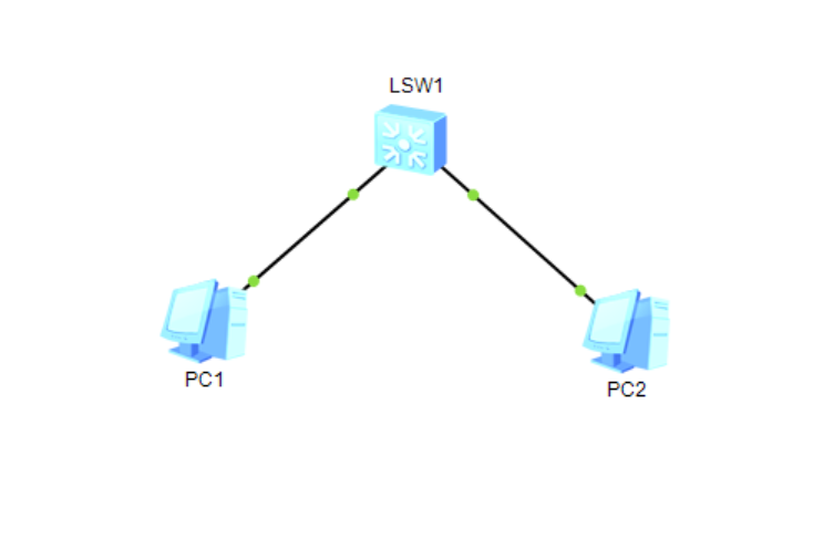
两台主机的配置分别如图所示:
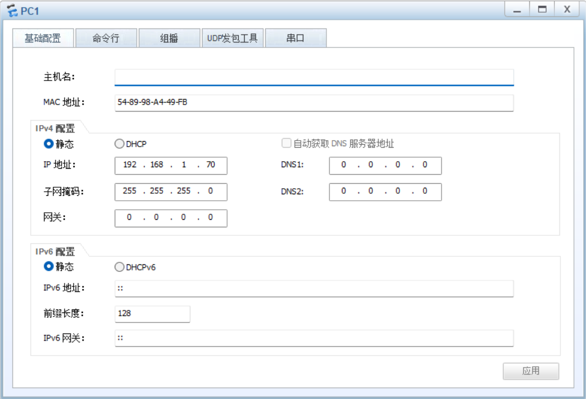
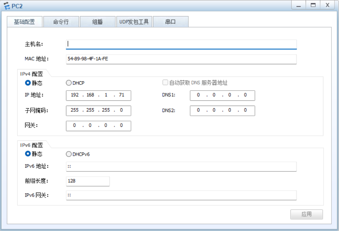
子网掩码全部选择255.255.255.0,IP地址最后一位取不同数字。注意到由于使用的是交换机,作为二层设备,所有端口在同一个广播域,通过MAC地址直接通信,不需要IP网关。如果错误地设置了网关可能导致报错:Destination host unreachable.
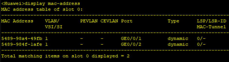
在两台主机上分别确认互相ping通后,在交换机窗口中使用命令display mac-address来得到交换机的转发表:
结构2:
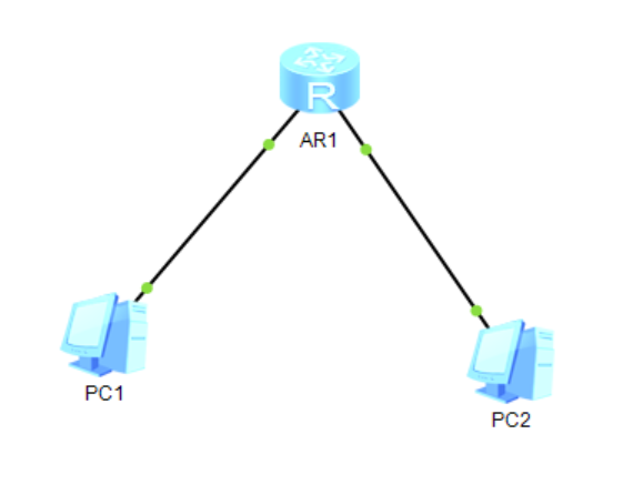
两台主机的配置分别如图所示:
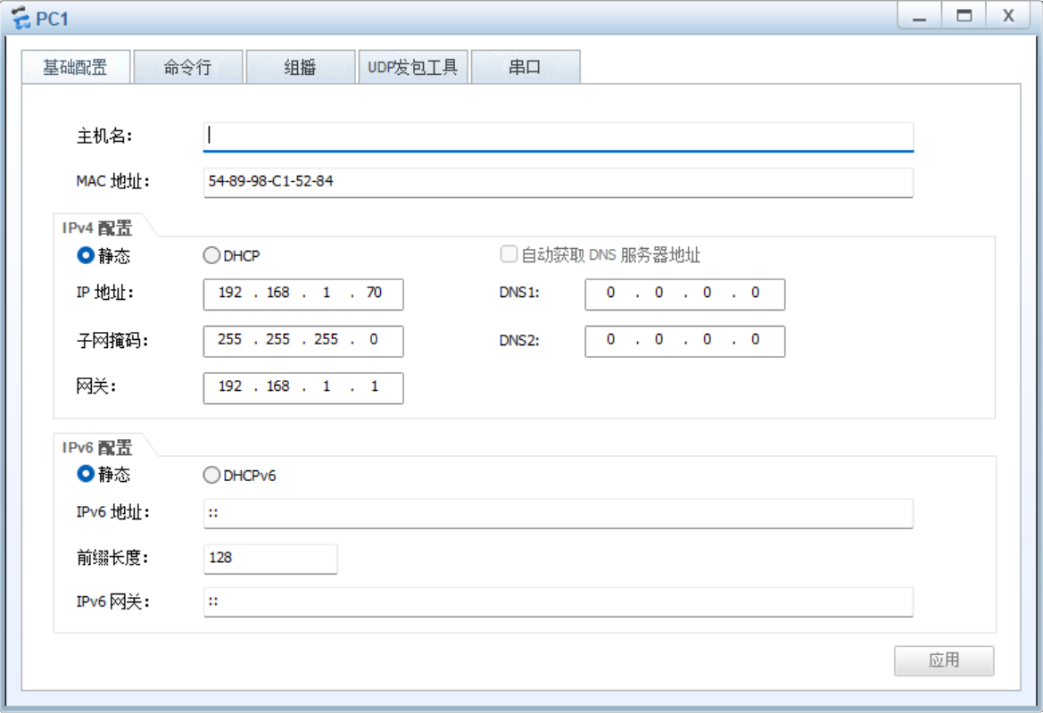
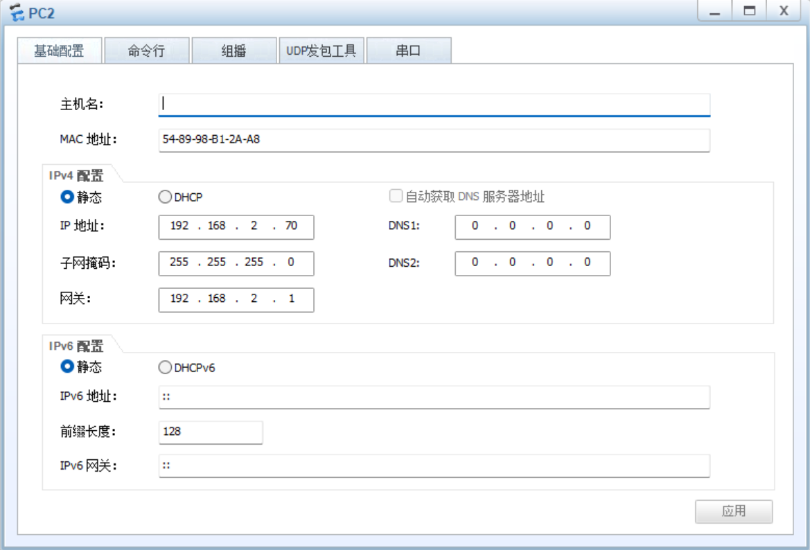
注意到此处网关是需要设置的,而且两台主机的网关不同,这一点与结构1中的交换机有显著区别。路由器是三层设备,每个接口是不同的广播域,通过IP地址路由转发而不是通过MAC地址直接通信,因此需设置不同网关。
其次需要注意的是IP地址与网关之间的对应关系。网关代表了一个网段,如H1的192.168.1.1代表192.168.1.0~192.168.1.255,因此IP地址192.168.1.70显然在网段内,但如果将第三位换成2,则会被认为不在同一个网段内导致报错。
结构1中的交换机无需配置,而此处的路由器则需要经过配置才能正常工作,具体配置过程代码如下:
<Huawei>system-view
Enter system view, return user view with Ctrl+Z.

[Huawei]interface GigabitEthernet 0/0/0
[Huawei-GigabitEthernet0/0/0]ip address 192.168.1.1 255.255.255.0
[Huawei-GigabitEthernet0/0/0]quit

[Huawei]interface GigabitEthernet 0/0/1
[Huawei-GigabitEthernet0/0/1]ip address 192.168.2.1 255.255.255.0
[Huawei-GigabitEthernet0/0/1]quit

[Huawei]quit

<Huawei>save
The current configuration will be written to the device.
Are you sure to continue?[Y/N]y
Now saving the current configuration to the slot 0
Save the configuration successfully.
注意配置端口ip地址需先进入端口视图,如指令interface GigabitEthernet 0/0/0,这里的端口取决于具体连接的端口。这里选择的AR2220型路由器有GigabitEthernet 0/0/0、GigabitEthernet 0/0/1、GigabitEthernet 0/0/2三个端口。连接的端口可通过将鼠标移到连线上来查看:
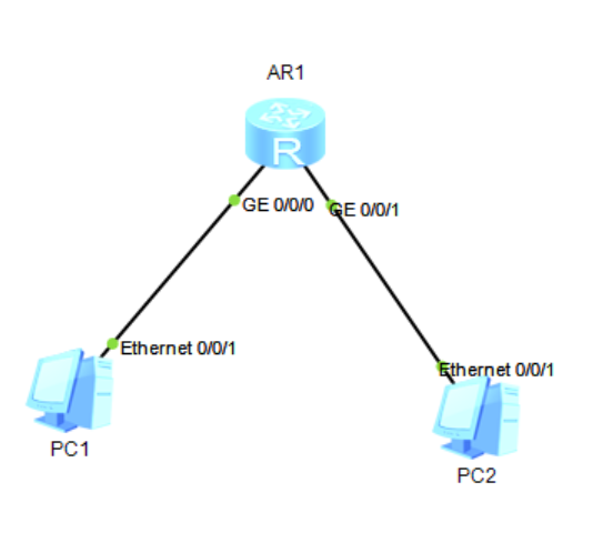
最后要记得逐层退出并保存。
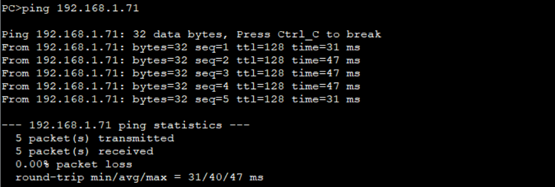
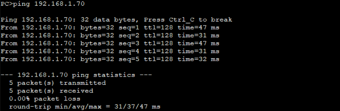
最后通过ping通确认网络正常工作:
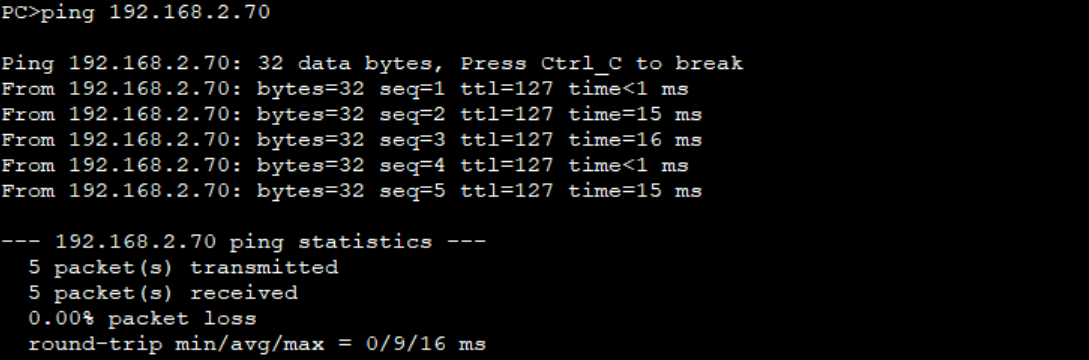
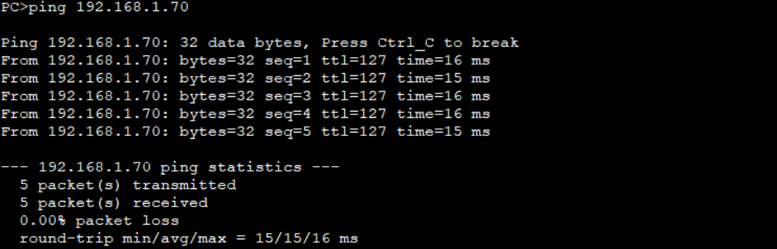
结构3:
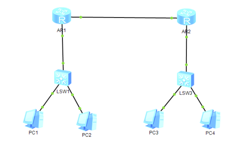
四台主机的配置分别如图所示:
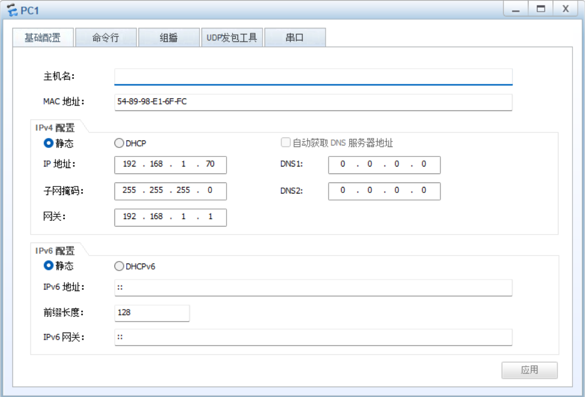
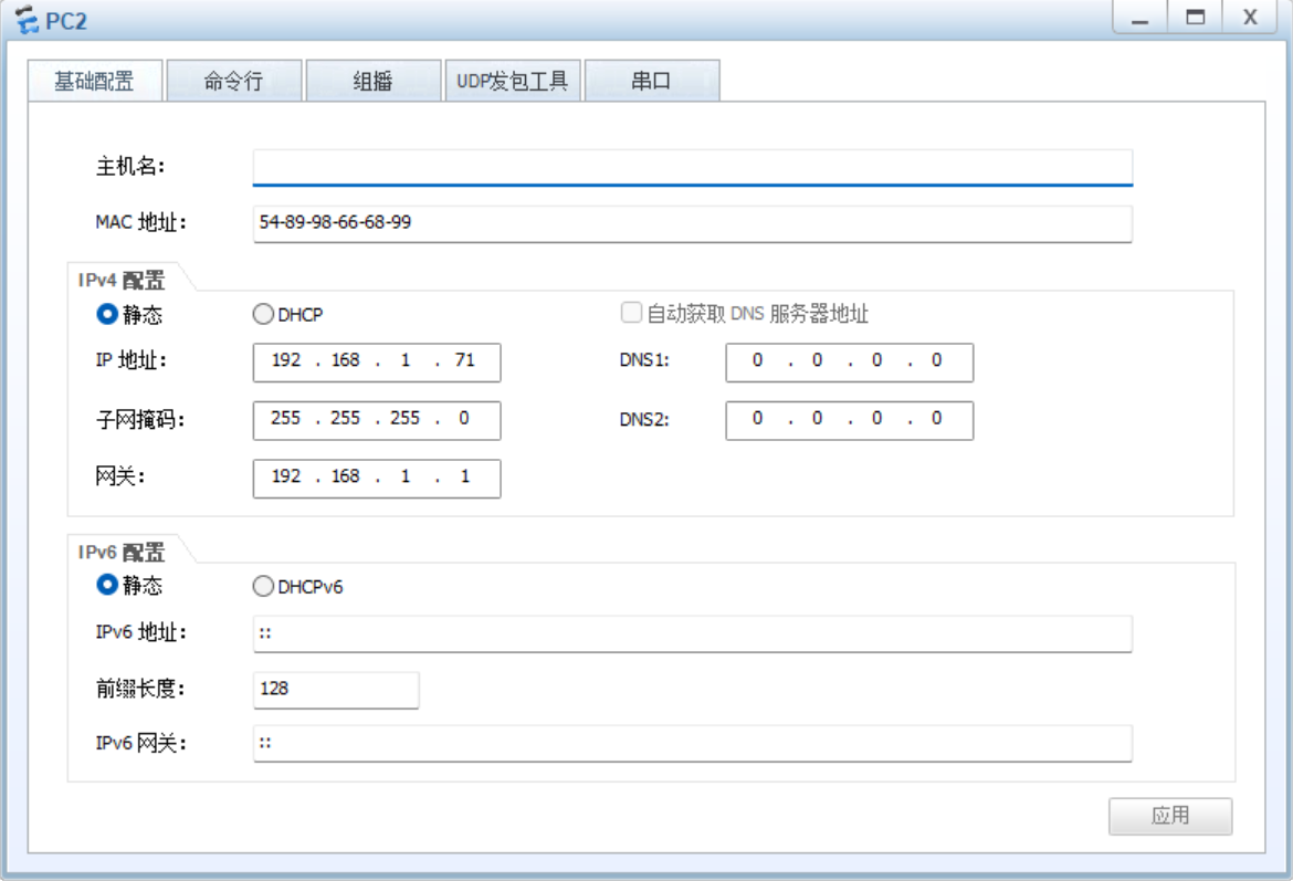
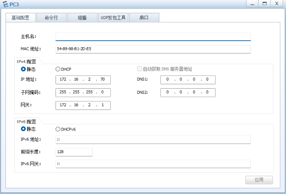
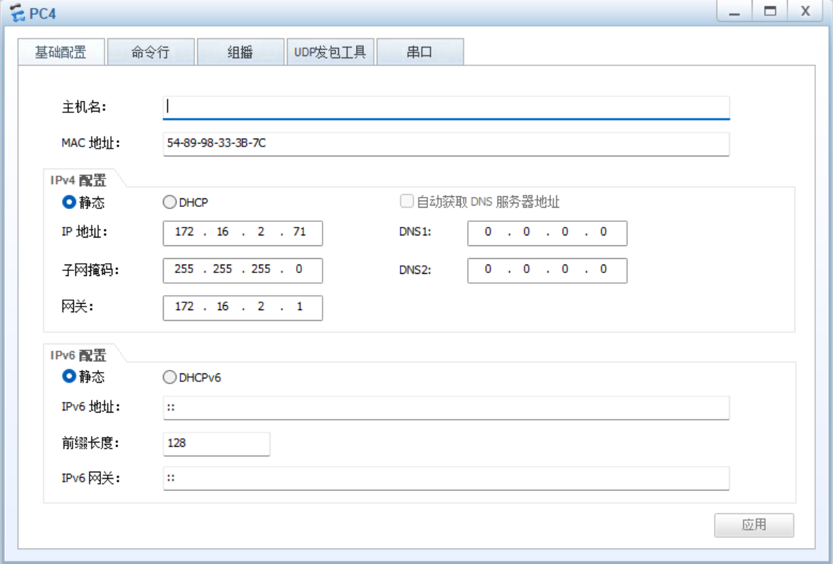
注意到这里H1、H2共用一个网关,H3、H4共用一个网关,两个网关互不相同。
R1配置:
<Huawei>system-view
Enter system view, return user view with Ctrl+Z.
[Huawei]interface GigabitEthernet 0/0/0
[Huawei-GigabitEthernet0/0/0]ip address 192.168.1.1 255.255.255.0
[Huawei-GigabitEthernet0/0/0]quit

[Huawei]interface GigabitEthernet 0/0/1
[Huawei-GigabitEthernet0/0/1]ip address 10.0.0.70 255.255.255.0
[Huawei-GigabitEthernet0/0/1]quit

[Huawei]ip route-static 172.16.2.0 255.255.255.0 10.0.0.71
[Huawei]quit

<Huawei>save
The current configuration will be written to the device.
Are you sure to continue?[Y/N]y
Now saving the current configuration to the slot 0
Save the configuration successfully.
R2配置:
<Huawei>system-view
Enter system view, return user view with Ctrl+Z.
[Huawei]interface GigabitEthernet 0/0/0
[Huawei-GigabitEthernet0/0/0]ip address 172.16.2.1 255.255.255.0
[Huawei-GigabitEthernet0/0/0]quit

[Huawei]interface GigabitEthernet 0/0/1
[Huawei-GigabitEthernet0/0/1]ip address 10.0.0.71 255.255.255.0
[Huawei-GigabitEthernet0/0/1]quit

[Huawei]ip route-static 192.168.1.0 255.255.255.0 10.0.0.70
[Huawei]quit

<Huawei>save
The current configuration will be written to the device.
Are you sure to continue?[Y/N]y
Now saving the current configuration to the slot 0
Save the configuration successfully.
此处相比结构2多出了配置路由表步骤,即指令ip route-static A B C。A指最终目的地,例如对于R1来说最终需要将数据送到172.16.2.0网段;B是子网掩码;C是下一跳(next hop),例如R1需要先将数据传送到R2的0/0/1端口IP10.0.0.71。这里端口使用的较多,尤其需要注意配置的和实际连接的是否相对应,否则很容易产生报错。
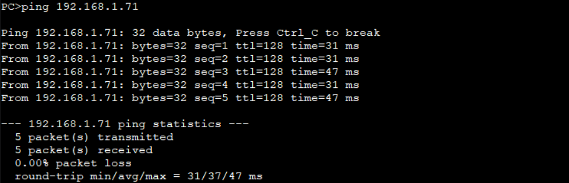
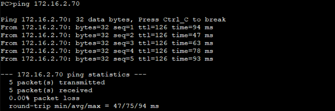
最后通过H1pingH2(通过交换机)、H1pingH3(跨路由)来验证网络是否正常工作:
补充:
路由器常用命令:
system-view - 进入系统视图
interface GigabitEthernet0/0/0 - 进入端口视图
ip address 192.168.1.1 255.255.255.0 - 配置端口ip地址
ip route-static 192.168.2.0 255.255.255.0 192.168.2.1 - 配置路由表
display interface - 显示接口配置信息(ip地址配置等)
display ip routing-table - 显示路由表
display ip interface brief - 显示路由端口ip配置
display arp all - 查看arp表
交换机常用命令:
display mac-address - 查看交换机转发表(部分型号支持)
display forwarding-table - 查看交换机转发表(部分型号支持)

腾讯云面向开发者汇聚海量精品云计算使用和开发经验,营造开放的云计算技术生态圈。
更多推荐
 10
10 0
0- 0


 已为社区贡献1条内容

所有评论(0)